ASME Pressure Vessel Connections
The Nozzle Experts
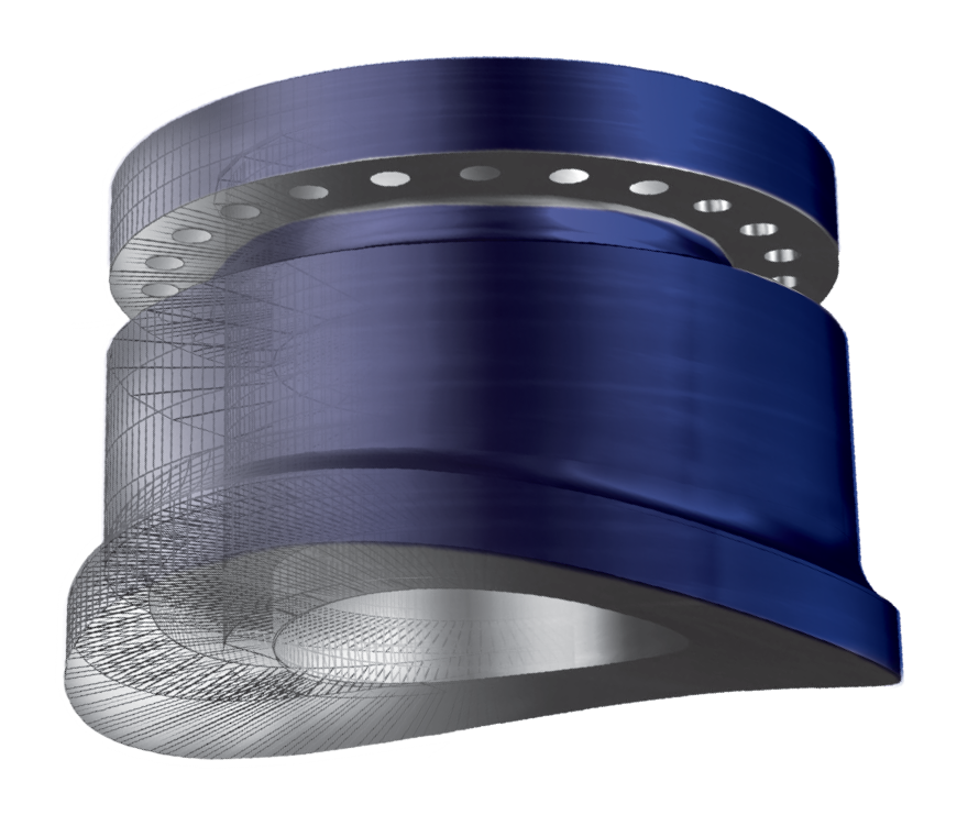
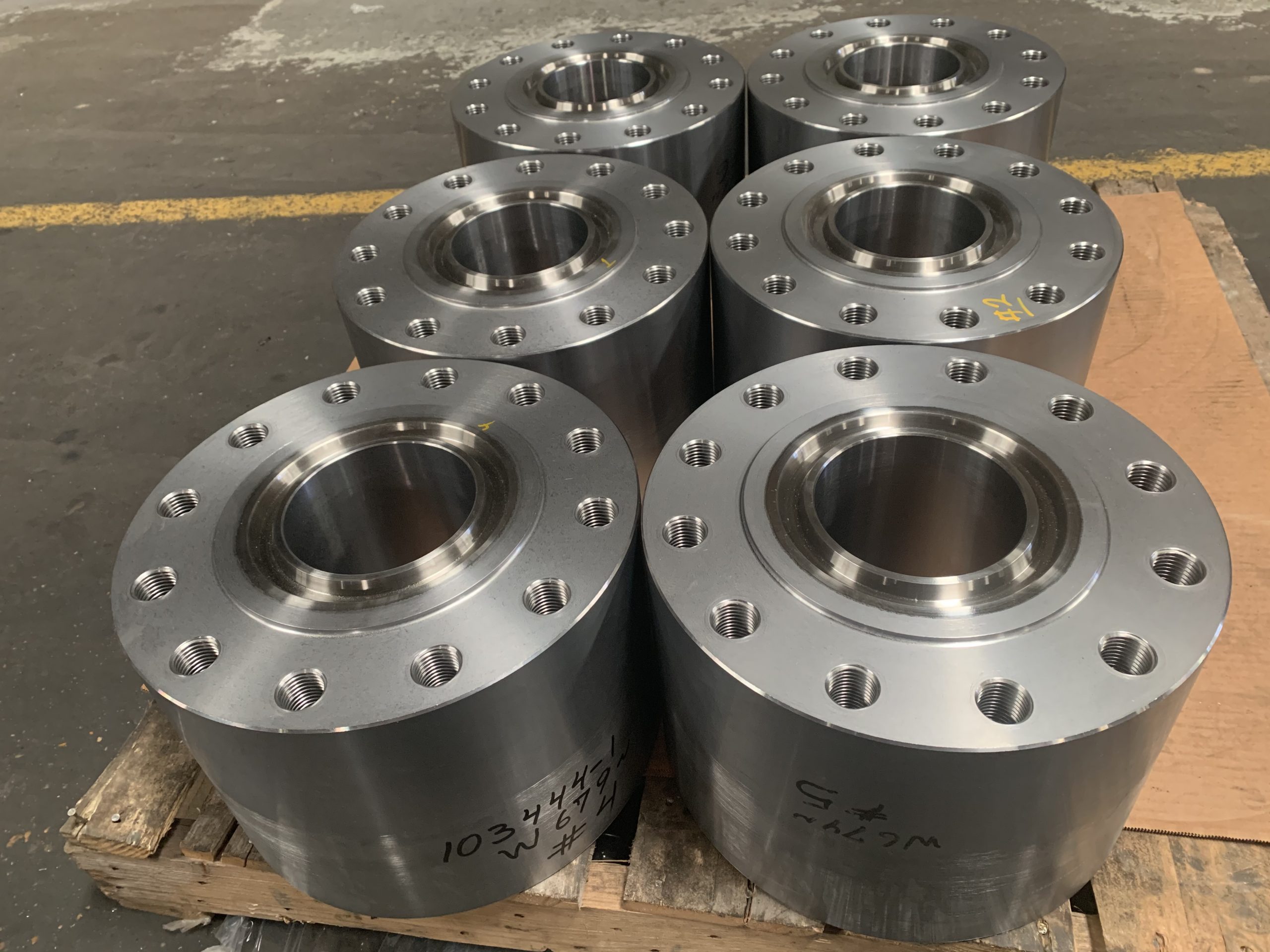
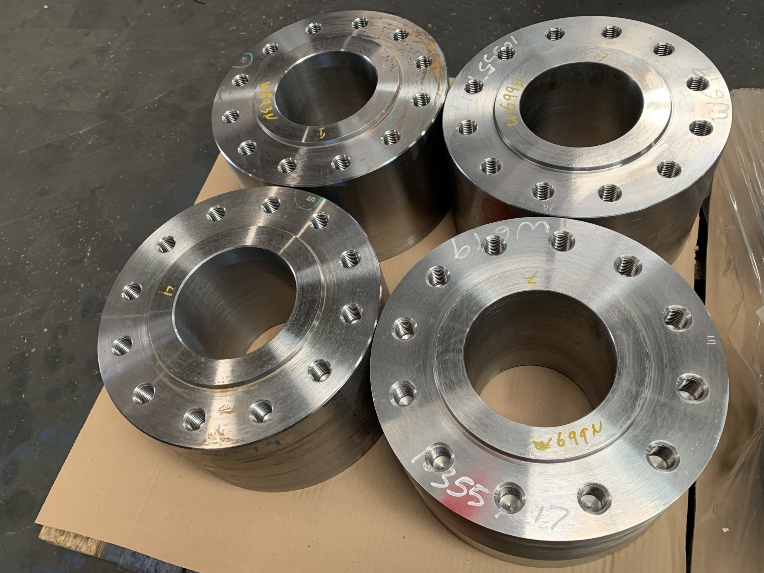
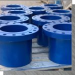
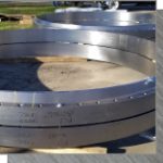
Studding Outlets
A studding outlet provides a unique compact design with inherent reinforcement offering distinct advantages to designers and fabricators. The low profile of this connection provides for the lowest projection of a bolted connection where clearance may be a factor in connection selection.
The outside diameter and/or body thickness may be increased where additional reinforcement is required. In addition, the studding outlet can be supplied with an optional contoured bottom and/or Q-lip for simplified installation and reduction in cost of positional welding. The studding outlet is the most economical of bolted connections.
Catalog & Diagrams – Click Here
Codes: FCI Studding Outlets are manufactured in compliance with ASME Section II, Section VIII, Div. 1, and ASME B16.5. Products may be ordered to special requirements or other standard codes such as ASME Section I, III and Section VIII, Div. 2, ASME B31.1 or B31.7.
Materials: All materials comply with the applicable ASME and ASTM specifications. Full traceability is mandated by our quality system. Standard forged material is carbon steel SA105. Connections can also be furnished in other carbon steels, alloy steels, stainless, high nickel and non-ferrous alloys upon request.
Bores: Facing: Standard studding outlet bores are equal to their nominal flange/pipe size. Special bores are available upon request.
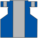
Thickness: Listed thickness “T” dimensions in FCI charts are the minimums required per ASME Section VIII Div. 1 for thread engagement and thickness required for installing studding outlets to the inside diameter of vessel shells, heads, cones, pipes, etc. as shown in Figures A, B, C, and D of typical attachment styles for studding outlet connections.
For “through-type” installations as per Fig. B and per Fig. C, thickness “T” must generally be increased in accordance with the requirements of the ASME Code, Section VIII, Div. 1, paragraph UG-43(d), to provide additional material under the drilled and tapped holes of the studding outlet.
Surface mounted “set-on” studding outlets, as shown in Figures E, F and G, generally require a thickness less than that listed in accordance with ASME Code design.
Studding outlets will be priced and produced to other than the FCI listed thickness “T” at Purchaser’s request. In all cases, Purchaser shall design and advise FCI of the required thickness “T” dimension.
Body: Studding outlet body outside diameters are equal to the outside diameters of flanges, as specified in ASME B16.5 for the size and class of connection ordered. Upon request, studding outlet outside diameters may be increased to satisfy reinforcing requirements. Standard FCI studding outlet mating connection ends will be manufactured in accordance with ASME B16.5 flange and drilling dimensions. Drilled holes will be tapped in accordance with ASME Section VIII, Div. 1, paragraph UG-43(g). Bolt holes will straddle natural centerlines, unless specified otherwise. Studs, bolts, nuts, and gaskets are not furnished.
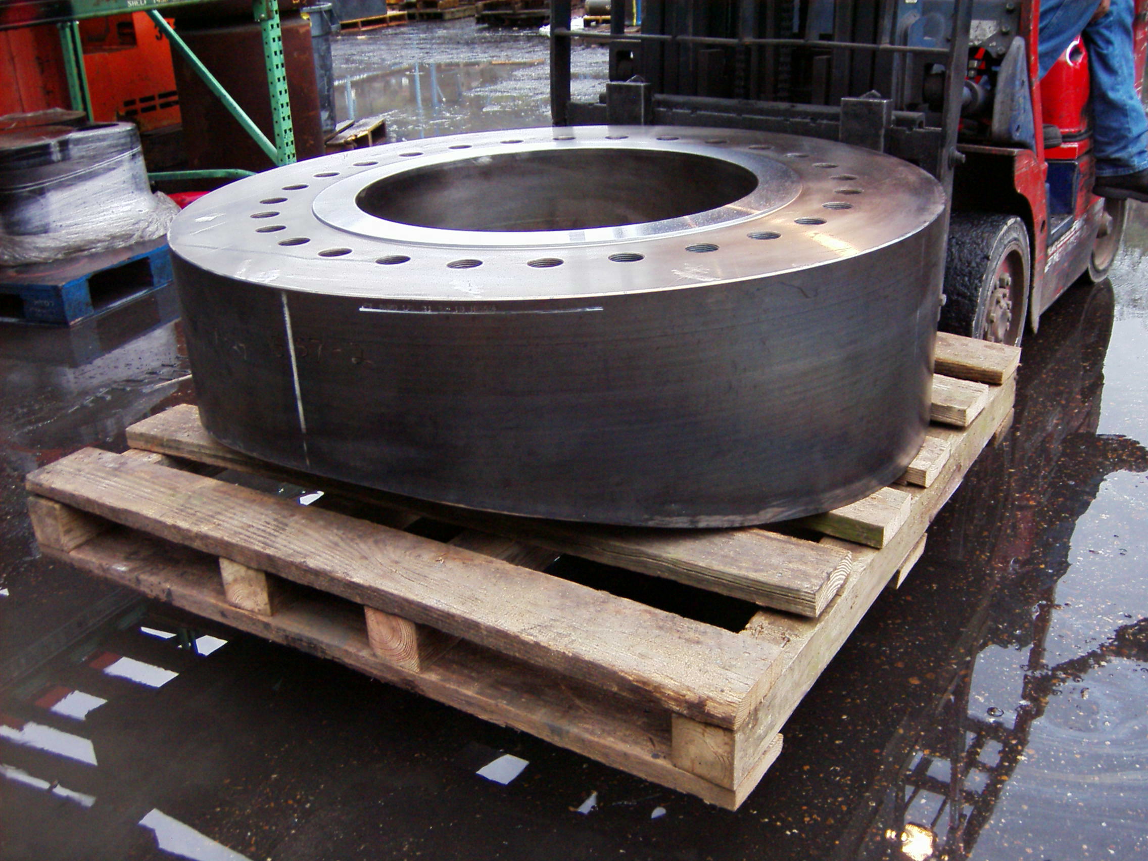
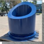
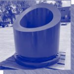
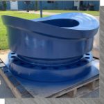
Contoured Bottoms: Studding outlet connections will be furnished with flat bottoms unless specified otherwise. All connections are available with optional “contoured” bottoms for installation in shells, heads and cones. In these cases, the minimum thickness “T” will be measured from the studding outlet face to the bottom contour of the connection. See preceding thickness note and typical attachment style as shown on following page.
Tolerance for bottom contouring will be in accordance with ASME Section VIII, Div. 1, paragraph UG-80 out-of- roundness tolerance. Purchaser to specify when connections are to be surface mounted for special contouring requirements, such as Fig. F and Fig. G.
Wrap around” connections exceeding the outside diameter of the shell to which they are mounted will have the transverse pendant points square cut.Tangential/hillside, inclined, and other special contoured bottoms are available upon request.
Insert Lips: All studding outlet connections can be ordered with insert lips- “Q” type attachment.
Test Holes: Studding outlets may be ordered with test holes. Unless specified otherwise, test holes will be provided in accordance with Fig. E, ¼” diameter drilling and tapped with a 1/8” N.P.T.
Heat Treatment: All standard connections over Class 300 rating are supplied in the normalized condition in accordance with the requirements of ASME Section II. Other heat treatment requirements can be provided upon request.
Tolerance: Manufacturing tolerances, as a minimum, will meet the requirements of ASME B16.5 where applicable.
Reinforcement: Reinforcement must be provided to satisfy area requirements for all planes through the center of the opening normal to the vessel surface especially the voids created by the drilled and tapped holes of studding outlets. The area requirements, planes of reinforcement and the “F” factor are to be addressed by Purchaser’s designer in accordance with the ASME Code, Section VIII, Div. 1, paragraph UG-37. Increasing the thickness “T” and/or the outside diameter of the studding outlet connection may replace the area lost from the drilled and tapped holes. See following table for area loss of FCI standard studding outlet drilled and tapped holes:
| TAP SIZE (inches) |
DEPTH OF HOLE (inches) |
AREA (sq. inches) |
|---|---|---|
| 1/2 | 0.88 | 0.81 |
| 5/8 | 1.12 | 1.28 |
| 3/4 | 1.31 | 1.80 |
| 7/8 | 1.44 | 2.29 |
| 1 | 1.56 | 2.82 |
| 1 1/8 | 1.81 | 3.69 |
| 1 1/4 | 2.12 | 4.83 |
| 1 3/8 | 2.25 | 5.62 |
| 1 1/2 | 2.38 | 6.47 |
| 1 5/8 | 2.56 | 7.53 |
| 1 3/4 | 2.81 | 8.92 |
| 1 7/8 | 3.00 | 10.19 |
| 2 | 3.31 | 12.04 |
| 2 1/4 | 3.56 | 14.50 |
| 2 1/2 | 4.00 | 16.13 |
| 2 3/4 | 4.38 | 21.82 |
| 3 | 4.62 | 25.02 |
| 3 1/2 | 5.38 | 33.99 |